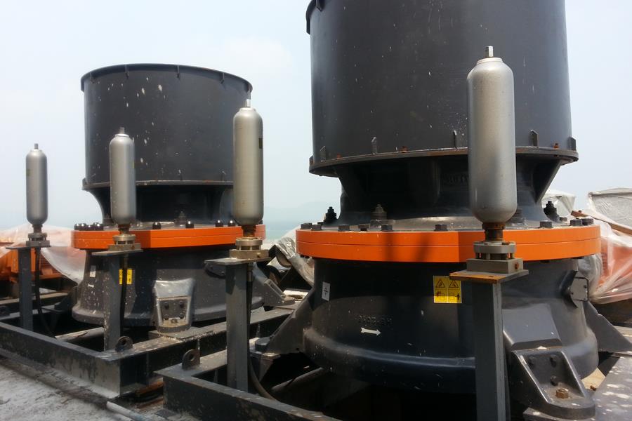
Structural Features of Vertical Impact Crusher
The structural features of the vertical impact crusher include the transmission system, main shaft assembly, impeller, feed hopper, distributor, vortex crushing chamber, base, lubrication system, and other components.
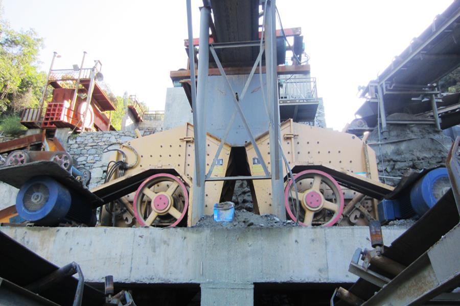
1. The transmission system adopts a belt drive structure driven by either a dual motor or a single motor. In the dual motor configuration, the two motors are installed on opposite sides of the main shaft assembly, with their pulleys connected to the main shaft pulley via a transmission belt, ensuring balanced force distribution on both sides of the main shaft and eliminating additional torque. In contrast, single-motor drive causes the main shaft to experience force from one side, resulting in additional torque. It is recommended to use dual-motor drive when the motor power exceeds 55 kW (per motor).
2. Main shaft assembly: The main shaft assembly is mounted on the base to transmit power from the motor via V-belts and support the rotational movement of the impeller. The main shaft assembly consists of a bearing housing, main shaft, and bearings.
3. Impeller: The impeller has a hollow cylindrical structure and is mounted on the upper shaft of the spindle assembly. It is connected via a tapered sleeve and key to transmit torque and rotates at high speed. The impeller is the core component of the PL vertical impact crusher. Mineral raw materials enter the impeller through the central feed pipe of the upper feed distributor. The material is evenly distributed to the various discharge channels of the impeller by the central distribution cone. Wear-resistant blocks made of special materials are installed at the discharge channel outlets. These blocks can be replaced once worn out. The impeller accelerates the material to a speed of 70–100 m/s and ejects it, impacting the mineral bed layer in the vortex crushing chamber to achieve intense self-crushing and destruction.
4. Feed hopper: The feed hopper has an inverted frustum structure, with a wear-resistant ring at the feed opening. Material from the feeding equipment enters the crusher through the feed hopper.
5. Distributor: The distributor is installed at the top of the vortex crushing chamber. Its function is to divert the feed material from the feed hopper, allowing part of the material to enter the impeller directly through the central feed pipe and be gradually accelerated to a high speed before being ejected, while another part of the material bypasses the central pipe and enters the outer side of the impeller in the vortex crushing chamber, where it is impacted and crushed by the high-speed material ejected from the impeller. This does not increase kinetic energy consumption, enhances production capacity, and improves crushing efficiency.
6. Vortex crushing chamber: The vortex crushing chamber consists of an annular space formed by upper and lower cylindrical sections. The upper and lower covers of the lower cylinder have two openings, with the upper section connected to the upper cylinder and the lower section connected to the discharge port. The impeller rotates at high speed within the vortex crushing chamber, which can also retain material to form a material bed layer. The crushing process occurs within the vortex crushing chamber, with the mineral bed layer isolating the crushing action from the chamber walls, limiting the crushing effect to material-to-material interactions while also serving as a wear-resistant self-lining. Observation holes are provided on the upper cylinder cover plate to monitor the wear condition of the wear-resistant blocks at the impeller flow channel discharge port and the wear condition of the lining plates at the top of the vortex crushing chamber. When the crusher is in operation, the observation holes must be tightly sealed. The distributor is fixed to the upper cylindrical section of the vortex crushing chamber. The airflow generated by the high-speed rotation of the impeller forms an internal airflow recirculation system within the vortex crushing chamber through the distributor and impeller.
7. Base: The vortex crushing chamber, main shaft assembly, motor, and transmission system are all mounted on the base. The central part of the base is a four-sided space for installing the main shaft assembly, with discharge channels formed on both sides of the four-sided space. Dual motors are installed at the longitudinal ends of the base, which can be mounted on a support frame or directly on the foundation.
8. Frame: Depending on the working environment of the crusher—open-air or indoor operations—users may choose to configure a frame or not.
9. Lubrication System: The system uses molybdenum disulphide dry oil lubrication. The lubrication points are the upper and lower bearings of the main shaft assembly. To facilitate oil injection, the machine uses oil pipes to route the oil cup to the exterior of the machine, and a dry oil pump is used for regular oil replenishment.
A vertical impact crusher typically consists of the above nine components, each of which is essential. We hope users will perform proper maintenance and upkeep of the impact crusher during use.
If you wish to learn more about this crusher, please click on the website customer service to consult for free immediately.