How to improve sand shape using cascade feed on VSI
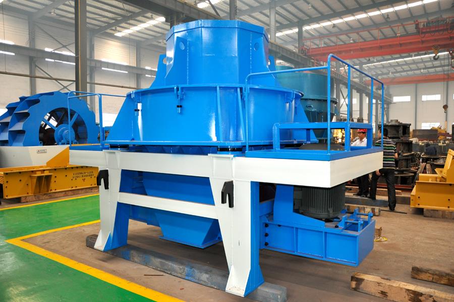
For manufactured sand producers worldwide, achieving a cubical, well‑graded product is essential for concrete workability and strength. A VSI (vertical shaft impactor) is the preferred machine for shaping sand, but many operators overlook a simple adjustment that significantly improves particle shape: cascade feed. Understanding how to improve sand shape using cascade feed on VSI allows you to produce more cubical sand while reducing rotor tip wear and energy consumption. OCP Mechanical Company, a factory‑direct manufacturer with over 40 years of experience, supplies Type V VSIs with adjustable cascade gates, backed by 24/7 online support.
Note: Product data are constantly updated; the latest specifications should be confirmed with our online customer service.
What is cascade feed and how does it work?
Cascade feed is a feature that bypasses a portion of the incoming material directly to the crushing chamber, without passing through the rotor. In a standard VSI, all feed goes through the rotor, is accelerated, and thrown against the rock chamber or anvils. With cascade feed, a manually or automatically adjusted gate allows 20‑40% of the feed to fall directly into the chamber, where it is struck by material exiting the rotor. This creates additional rock‑on‑rock impact, which improves particle shape. When you learn how to improve sand shape using cascade feed on VSI, you are essentially adding a second, gentler crushing mechanism that rounds edges without generating excessive fines.
Many sand producers have found that cascade feed reduces the flakiness index by 2‑4 percentage points, moving from 15‑18% to 11‑14%, without sacrificing throughput.
How cascade feed enhances particle shape
The rotor alone produces cubical particles, but some edges remain sharp or elongated. The rock‑on‑rock impact from cascade feed acts as a final shaping stage. Material falling through the cascade chute collides with high‑velocity particles exiting the rotor, rounding edges and breaking off protruding corners. This two‑stage impact produces a more uniform, cubical product. The improvement is most noticeable in the 0.6‑2.36 mm size range – critical for concrete sand.
When you master how to improve sand shape using cascade feed on VSI, you also reduce the amount of material that passes through the rotor, which lowers tip wear by 15‑25% and reduces energy consumption by 5‑10%. This makes cascade feed a highly cost‑effective adjustment.
How to set the optimal cascade ratio
The cascade ratio is the percentage of total feed that bypasses the rotor. Typical ratios range from 20% to 40%. To determine the best setting for your material:
Start with 25% cascade – Close the cascade gate to 0%, then open it until 25% of the feed bypasses the rotor (measured by belt scale or manual sampling).
Run for one hour – Take a sand sample and measure the flakiness index (e.g., using a caliper or shape analyzer).
Adjust in 5% increments – Increase cascade to 30% and retest. If shape improves, continue. If shape degrades or throughput drops, reduce to 20%.
Balance with wear – Monitor rotor tip wear. A higher cascade ratio reduces tip wear. Find the setting where shape meets your specification with acceptable tip life.
For hard, abrasive rock like granite or basalt, a cascade of 25‑30% is a widely used starting point. For softer rock like limestone, 15‑20% may suffice. Many operators have reduced tip consumption by 20‑30% while maintaining sand quality simply by optimizing cascade.
All performance and price information in this article is for reference only; contact our team for current, site‑specific data.
Cascade feed vs. rotor speed – which is more effective?
Both cascade feed and rotor speed affect sand shape, but they do so differently. Higher rotor speed (1,700‑1,900 rpm) increases impact energy, producing more cubical particles but also more fines and higher tip wear. Cascade feed improves shape without increasing fines or wear. For best results, combine a moderate rotor speed (1,500‑1,600 rpm) with a 25‑30% cascade. This approach reduces tip wear by 15‑25% compared to high‑speed operation without cascade, while achieving similar or better shape. When you understand how to improve sand shape using cascade feed on VSI, you realize it is often the most cost‑effective tuning parameter.
Practical considerations for cascade feed installation
Not all VSIs come with cascade feed as standard. OCP Type V VSIs include an adjustable cascade gate as an optional feature. The gate can be manual (hand‑wheel operated) or automated (connected to the VFD control panel). For automated cascade, the PLC adjusts the ratio based on feed rate and product shape feedback from an online particle analyzer (optional). For most operators, a manual gate with a position indicator is sufficient – you set it once per rock type and leave it.
Installation of cascade feed requires a split feed chute above the rotor. The main feed goes to the rotor, while the bypass feed drops directly into the chamber. Ensure the bypass chute is lined with wear‑resistant material (polyurethane or ceramic) to prevent contamination.
Why OCP is your partner for VSI optimization worldwide
Mastering how to improve sand shape using cascade feed on VSI gives you a powerful tool to produce higher‑value sand. OCP Mechanical Company has four decades of experience in VSI technology for global markets. Our 24/7 online team helps with cascade ratio tuning, rotor speed optimization, and wear monitoring. We invite you to request a no‑obligation quote and free VSI tuning consultation.
For a no‑obligation consultation on how to improve sand shape using cascade feed on VSI, simply click the live chat icon on this page. Our online customer service team is available 24 hours a day, 7 days a week, to provide free technical advice, equipment recommendations, and spare parts – helping you produce premium manufactured sand efficiently and profitably.