
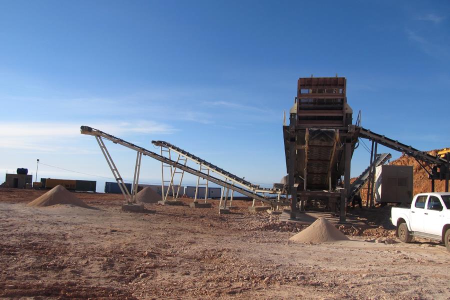
How to Balance a Cone Crusher After Mantle Replacement for 180 TPH
Why Balancing After Mantle Replacement Matters
Mantle replacement is one of the most critical maintenance operations in any cone crushing circuit. For a crusher running at 180 TPH, a poorly balanced machine after a mantle change will not simply underperform—it will generate excessive vibration, accelerate wear on the eccentric assembly, damage the main frame, and potentially cause catastrophic failure within days. A field case involving a Kubria G110 cone crusher illustrates the risk: after replacing the liners, the crusher exhibited vibration levels of 12 mm/s. The root cause was not the mantle itself but a 0.2 mm misalignment in the drive coupling, which destroyed the input shaft bearings within 48 hours. A simple laser alignment check would have prevented a $30,000 outage. The lesson is clear: balancing after mantle replacement is not limited to the mantle itself. It encompasses the entire rotating assembly, the drive train, and the crushing chamber geometry. OCP Mechanical Company, with over 40 years of manufacturing experience, supplies cone crushers and wear parts engineered for precision installation, backed by factory-direct pricing and responsive technical support.
Step 1: Verify Assembly Precision and Liner Fit
The foundation of post-replacement balance is precise assembly. After installing the new mantle, the fitting clearance between the mantle and the moving cone must be checked before the crusher is reassembled. Use a feeler gauge to verify that the gap between the liner and the cone body is close to zero and uniformly distributed around the circumference. The head nut must be tightened to the manufacturer‘s specified torque, and the mantle positioning grooves must align correctly. After the backing compound has fully cured, tighten the lock bolts symmetrically in a cross pattern to the torque specified in the equipment manual, then clear all debris, welding slag, and filler residue from the crushing chamber. If the mantle is not seated evenly on the head taper, the centre of gravity of the rotating assembly will shift, producing vibration that cannot be corrected by any amount of counterweight adjustment. Check the head taper surface for wear or galling before installation—if the surface finish exceeds Ra 0.8–1.6 μm, machining may be required to restore proper seating.
Step 2: Confirm Backing Compound Support and Curing
The backing compound between the mantle and the head serves two functions: it provides uniform support across the mantle‘s mounting surface and ensures that crushing forces are distributed evenly. When the backing compound is applied correctly and allowed to cure fully, it ensures that even pressure is applied on the outer surface of the mantle and the bowl liner. Incomplete curing or improper mixing will leave the mantle unsupported in certain areas, causing flexing and vibration under load. For zinc alloy backing, preheating the components to approximately 60°C–100°C is recommended to eliminate moisture and ensure a smooth cast. For epoxy resin backing, follow the manufacturer’s mixing ratio and pour temperature specifications precisely. After curing, verify that the fastening status remains secure after the first 6 to 8 hours of operation—any detected loosening must be tightened immediately to prevent “pounding” damage to the seating surfaces.
Step 3: Inspect the Drive Train and Eccentric Assembly
Balancing after mantle replacement is incomplete without a thorough inspection of the drive train and eccentric assembly. The eccentric assembly and bevel gears operate under tight tolerances, and the increased load from a new, tighter chamber profile can expose pre-existing misalignments that were previously masked by worn liners. Check the gear backlash during every liner change; for many cone crushers, this is typically 0.5–0.8 mm. If backlash has increased, it indicates thrust bearing wear, which allows the eccentric to drop and alters the crushing stroke. Inspect the countershaft alignment using a laser alignment tool—even a small misalignment can generate vibration that is mistakenly attributed to the mantle. Also check the counterweight and counterweight guard plates for wear or damage; these components are essential for neutralising the centrifugal forces generated by the gyrating mantle. If the counterweight is worn or damaged, it must be replaced or rebalanced before the crusher returns to service.
Step 4: Set the Initial Closed Side Setting
After the new mantle is installed and the crusher is reassembled, the initial closed side setting (CSS) must be recalibrated. Parameters from the worn old liner cannot be used directly, because the old mantle‘s inner surface had developed an even wear layer that gradually expanded the actual CSS under the same adjustment ring height. The standard procedure begins with a no-load trial run of 10–20 minutes to check that the main shaft and eccentric sleeve run without abnormal noise, and that the hydraulic or spring locking mechanisms operate smoothly without leakage or bouncing. Then, rotate the adjustment ring to set the initial CSS within a range of 1.3 to 1.6 times the controlled finished particle size. Measure the CSS at 4 to 6 evenly distributed points around the crushing chamber using lead block or laser equipment. If the dimensional differences among circumferential points exceed allowable tolerances—≤25% for spring cone crushers and ≤20% for single-cylinder hydraulic cone crushers—shut down the unit and inspect the support sleeve levelness and liner flatness before re-adjusting.
Step 5: Run-In and Vibration Verification
The final step in balancing is the controlled run-in procedure with vibration monitoring. Run the crusher empty for 30 minutes, monitoring bearing temperatures and vibration levels. Then introduce feed at 50% of rated capacity for 2 hours, followed by 75% for 2 hours, before ramping up to full 180 TPH production. Vibration should be measured at the main frame and eccentric housing; acceptable levels vary by crusher model, but any reading exceeding 12 mm/s indicates a problem that requires immediate investigation. Sources of post-replacement vibration include uneven mantle seating, loose fasteners, backing compound voids, drive misalignment, or worn eccentric bushings. If vibration persists after verifying assembly and alignment, inspect the eccentric bushing clearance—maximum allowable clearance is typically 0.2 mm over nominal. Re-check the CSS after the first 8 hours of production and retorque all fasteners.
OCP Mechanical Company: Factory-Direct Wear Parts and Crushing Solutions
With over 40 years of manufacturing experience, OCP Mechanical Company supplies cone crusher mantles, bowl liners, eccentric assemblies, and complete crushing and screening plants engineered for precision installation and reliable operation. Our wear parts are manufactured from high-quality manganese steel in Mn13Cr2, Mn18Cr2, and Mn22Cr2 grades, with dimensional tolerances that ensure proper seating and uniform support. As a direct factory manufacturer, we eliminate distributor margins, passing the savings directly to you. All price information provided is for reference only; final quotes depend on wear part specifications, equipment configuration, shipping terms, and current exchange rates. Our engineering team can recommend the optimal liner profile and replacement interval based on your specific ore characteristics, crusher model, and production targets. Product specifications are continuously updated; please consult our online customer service for the latest technical parameters tailored to your application.
Your Next Step: Get Expert Guidance and a Custom Quote
Balancing a cone crusher after mantle replacement for 180 TPH requires disciplined attention to assembly precision, backing compound curing, drive train alignment, CSS calibration, and run-in verification. Skipping any of these steps risks vibration, accelerated wear, and costly unplanned downtime. OCP Mechanical Company offers factory-direct, high-quality cone crusher wear parts and complete crushing solutions engineered for durability and low total cost of ownership—all at competitive prices. Our online customer service is available 24 hours a day, seven days a week, to provide free consultations, updated price references, and equipment selection guidance. Click the chat button now to discuss your project with a specialist—we are ready to help you build a more efficient and profitable crushing operation.
-
ASTEC Showcases A-Series Jaw Crushers at bauma CONEXPO INDIA 2026
-
Weir Secures Brightstar Crushing Plant Order with ENDURON® Crushers
-
AI-Powered Mineral Exploration Takes Center Stage at China Mining Conference 2026
-
OCP Showcases C6X Jaw Crusher and VSI6X Sand Maker at China Mining Conference
-
Europe's Sand Recovery Breakthrough: 300 TPH Washed Rock Fines